Iron and steel support in underground mining
Iron and steel support in underground mining
Iron and steel are used in mines in the form of rigid and yielding props, beams and girders, reinforcement in concrete, corrugated sheets and roof/floor bolts.
Steel props used in the miners are:
a) Rigid props
b) Yielding props
An ordinary Horizontal section steel girder of suitable length with the web cutaway and flanges turned over at one or both ends is the common type of rigid prop. If the prop buckles in use it can be straightened by hydraulic pressure situated at the pit bottom. Another timber core through major length extending 25 to 40 mm beyond the steel pipe at either end. The timber core yields to some extent to the roof weight.
Yielding Props:
1. Friction Props
MAMC Friction Props: The friction props type FP3 manufactured by M.A.M.C. consists of two seamless steel tubes of which the inner member is made captive to the outer member by means of a spring locking pin which prevents the inner member to come out completely from the outer member beyond the extended length.
The clamp unit which is fixed at the top of the outer member provides the necessary friction grip by hammering two locking wedges alternately. The inner member and the clamp unit are provided with special coatings which give the required frictional characteristics of the props and at the same time prevent from corrosion. In the closed position of the props adequate finger clearance has been given to avoid the injury to miner’s hand during operation.
The important features of these props are as follows:
- These are early bearing props and accept the roof and load very quickly.
- These have constant load yield characteristics.
- The weights of these props compared to their nominal load are less in comparison with other types of props.
2. Hydraulic props
A hydraulic prop is simply a hydraulic jack. These props have been used at longwall mechanised faces in our country. A hydraulic prof can be set to take immediately three quarters of the maximum load (yield load), but when overloaded it will yield at the designed load after which the resistance is uniform and about 3/4th of the maximum.
A hydraulic prop basically consists of two oil-filled cylinders, the upper one telescoping into the lower one. A piston head is fitted to the lower end of the top member and this provides a seal with the inside wall of the outer cylinder.
The piston (and the top members to which it is fitted) does to slide down, unless the load on it exceeds certain limits. The resistance to downward movement of the upper member is provided by the pressure of the oil in the cylinders and this oil pressure builds up by the operation of a pump at the time of setting up the prop in the piston.
There are two ways of building up the oil pressure in the prop by a pump:
(a) Closed circuit system.
(b) Open circuit system.
In the closed circuit system, a built-in pump is provided in the prop itself and forms an integral part of it. The pump is operated by an external detachable handle. In the open circuit system an external pump, serving a number of props from one central site, is connected to the prop by high pressure hose pipes and operation of the pump builds up the pressure of oil contained in the cylinders of the prop. Non-return valves provided on the prop retain the oil pressure.
The MAMC hydraulic prop consist essentially of an inner tube, a pump cylinder with oil, a guard tube, a release valve, a non-return valve, a main piston, a top extension fitting, and a pump and release shaft. The inner tube and pressure cylinder can be extended like a ram by hydraulic pressure. The pump can be actuated by an outside key or handle.
A large diameter steel tube connects the lower reservoir with a relief valve capsule. Action of the handle pumps the oil from the inner tube to the outer tube, thus extending the inner tube. After the prop has been so extended up to the roof, further operation of the pump handle provides the initial bearing pressure (or initial setting load) which is 5-8 tonnes.
The pumps handle is then withdrawn. In course of time when the roof pressure on the prop gradually increases the inner tube will not slide down till the load is 40 te, (in the case of 40-te prop) as the hydraulic fluid is compressed till that load is reached. When the load on the prop exceeds 40 te, a relief valve operates.
The relief valve is a capsule permitting adjustment and testing prior to insertion in the prop and it is set to the correct yielding pressure before the prop is assembled in the factory. During the yield, the oil pressure may be from 200 to 500 kgf/ cm2.
The prop can be withdrawn easily by pulling the release shackle, which actuates a cam and lifts the valve assembly off its seating, allowing a free flow of oil back to the top reservoir. Withdrawal can be effected from a distance by attaching a chain to the relief valve shackle and pulling it.
A hydraulic prop can be tightened in a few seconds to any length within a wide range. The pump handle is the only tool required for operation and the prop can be released and withdrawn in a few seconds.
The hydraulic oil used may be water with 10% suitable oil. The oil is DTE light oil, servo system 311 supplied by Indian Oil Corporation. In has anticorrosive characteristics.
M.A.M.C. manufactures 40-te props of its own design.
A precaution that must be borne in mind in connection with hydraulic props is that they must not be left lying on the floor, and the prop must be withdrawn before full closure i.e., before it becomes “solid”. On longwall faces having sand stowing, hydraulic props which were not used carefully, developed scratches due to sand rubbing on the inner cylinder thereby partially losing the oil-sealing capacity. Such neglect renders the prop ineffective.
Self-Advancing or Walking Supports:
- 4-Leg and 6-Leg Canopy Supports:
- Anti-Slew Equipment:
- Shield Supports:
- Steel Arches:
A workman is not required to handle the supports during any of these processes, except for guiding the roof bars supported by the hydraulic props. The self-advancing supports are used in coal mines on prop-free front long wall faces and are introduced for the first time in India in Monidih colliery.
The walking ability of a powered roof support is provided as follows- There are two distinctive sets of one to four hydraulic props connected by a common roof canopy and floor base. The sets are connected at the base by a horizontal shifting cylinder.
The support moves or “walks” when one set of props or “legs” is lowered and the shifting cylinder is actuated, while the other set of legs remain firm against the roof. After the first set moves through a predetermined distance, approximately 0.6 metre, its legs are set against the roof.
The same operations are now repeated for the second set, such that the whole support is self-advanced through an approximate distance of 0.6 metre. The face conveyor is advanced by the double acting rams set between the supports, usually in alternate support units.
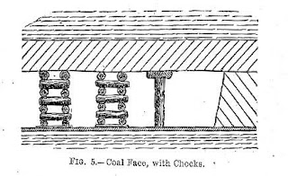
A combination of 2, 4 or 6 hydraulic props on a common rigid base is manufactured by some companies to provide support which can withstand very heavy roof pressure. The 6-leg support has particular application in coal seams between 1450 mm and 2360 mm in thickness. The legs may be single telescopic or double telescopic. A 4-leg support is bulkier than 6-leg support and is available for yield load of 310 te, 590 te, and 728 te.
These supports provide a canopy to the armoured chain conveyor and the coal cutter or shearer mounted on it. Between two units of such supports there is a gap of only 70 to 150 mm so that the entire face is well supported and there is no exposed roof along the length of the coal face.
Such heavy support are retracted, advanced and are re-erected by hydraulic pressure with the help of rams, (one ram serving one support) by the workers standing under the adjacent support. Operation is effected by a single lever ‘Dead Man’s Handle’ type control valve.
The support is attached to the armoured flexible conveyor (A.F.C) by a double acting hydraulic ram which gives a 6.3 tonne differential push load for conveyor advance, and 7.9 tonne pull load for support advance and has a 787 mm stroke.
Such supports can be fitted with anti-slew equipment and provision is made for attaching brackets to the base for it. Sliding links act on a guide rail between two chocks to maintain alignment. The guide rails are attached to the conveyor between alternate chocks.
The shield supports provides a continuous cover all along the face by canopies placed side by side. In this respect it is like the multi-leg hydraulic chock support except for a little difference in construction at the rear side i.e., the goaf side.
The hydraulic powered chock has a Venetian blind type flushing shield suspended from the rear of the main canopy to protect the chock from the falling debris of the goaf side whereas a shield has a sloping rigid one-piece roof of adjustable inclination on the goaf side. This results in elimination of side loading on the legs.
The shield supports are with 4 legs (not with six) which react direct with the canopy. The base of the shield is of rigid construction incorporating fabricated sockets for locating the legs. The lemniscale linkage-formed by the shield structure and links limits the movements of the canopy in the face towards goaf. The linkage also resists forces exerted on the canopy by horizontal movement of the roof.
Where mining conditions are suitable, i.e. sound roof with minimal lateral roof movement, then a chock type support could be the answer at a considerable cost saving over a shield. One type of shield support marketed by Downty is 4-leg, 400 te sub-level caving shield support. It is suitable for sub-level caving in thick seams or for conventional operations in longwall installations.
Apertures are provided in roof canopy of the shield for drilling of large coal lumps and subsequent blasting. The sloping shield has an integral coal loading door which is hydraulically controlled from a safe position within the support and can be closed at any time during coal entry. The shield also protects the rear conveyor from falling debris.
A hydraulically operated agitator arms is fitted to the rear shield to assist the flow of coal, if it does not fracture readily. Hydraulically operated canopy side flamps effectively seal the gaps between the supports and further exclude the dirt and dust from entering the working area. The support provides a clear traveling way in front of the legs from which all major operations can be controlled.
Hydraulic shields are costlier than chock supports.
These are used for supports of permanent and semi-permanent roadways. Heavy section rails in two parts are suitably shaped in workshop to form an inverted U when assembled together. The two sections, after installation underground in the place of erection, are joined 6y fishplates and four bolts and nuts.
The legs are generally placed in holes made in the floor. Normally no sole plate or lid is placed at the foot of arches and the arch has no yielding property. Where a roadway has to be supported by a number of steel arches, struts are placed between adjacent arches to prevent lateral shifting. To keep arches in contact with the roof and sides wooden laggings are placed on the top and sides in the same manner as for timber supports.
In Indian mines steel arches are not erected in places where strata may have a tendency to descend, and such arches with yielding property are not required.
C.G.I, sheets are used in the mines mostly to cover bars of girders over which cogs may be erected for support of a high roof, or sand/boiler ash may be filled to pack up a cavity in the roof in a mine.
 |
| Steel props |
 |
| hydraulic roof support/chocked shield support |
 |
| Steel arches |
 |
| Steel arches |


Comments
Post a Comment